SDTR1103CAP-0238J
X/X/Y axis SMD Drop Resistant RFID...
5,00 €
230 In Stock
Menus


| Freq. (kHz) | L (mH) | Q Min | Sensitivity (mVpp/App/m) Min | Height (mm) | Length (mm) | Width (mm) | SRF (kHz) Min | Tolerance | Cres (pF) | DCR (Ω) Max |
|---|---|---|---|---|---|---|---|---|---|---|
| 125 | 2.38 | 45 | 45 | 2.7 | 11.9 | 3.9 | 500 | ±5% | 680 | 27.5 |
| 125 | 4.91 | 36 | 50 | 2.7 | 11.9 | 3.9 | 380 | ±5% | 330 | 68 |
| 125 | 7.20 | 39.5 | 70 | 2.7 | 11.9 | 3.9 | 300 | ±5% | 220 | 82 |
| 125 | 9.00 | 40.5 | 80 | 2.7 | 11.9 | 3.9 | 300 | ±5% | 180 | 92 |
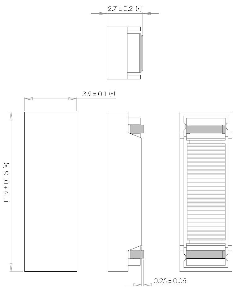
The SDTR1103CAP Series of Surface Mount ferrite wound inductor is the best solution when high electrical and mechanical performance is needed. Its length and cross sectional area are optimized to achieve the maximum sensitivity in the coil axis. The construction of the coil offer high mechanical performance due to the plastic base and ferrite laminate.
High stability in temperature, ranges:
|
The specification chart is a reference guide for the most common required values at working frequencies of 125 kHz. Any other inductance value at LF or tighter tolerances can be provided. Please contact our sales deparment for any inquiry.
| L (mH) | Tolerance | Q Min | Frequency (kHz) | Cres (pF) | SRF (kHz) Min | DCR (Ω) Max | Sensitivity (mVpp/App/m) Min | Length (mm) | Width (mm) | Height (mm) | |
|---|---|---|---|---|---|---|---|---|---|---|---|
| SDTR1103CAP-0238J | 2.38 | ± 5% | 45 | 125 | 680 | 500 | 27.5 | 45 | 11.9 | 3.9 | 2.7 |
| SDTR1103CAP-0491J | 4.91 | ± 5% | 36 | 125 | 330 | 380 | 68 | 50 | 11.9 | 3.9 | 2.7 |
| SDTR1103CAP-0720J | 7.20 | ± 5% | 39.5 | 125 | 220 | 300 | 82 | 70 | 11.9 | 3.9 | 2.7 |
| SDTR1103CAP-0900J | 9.00 | ± 5% | 40.5 | 125 | 180 | 300 | 92 | 80 | 11.9 | 3.9 | 2.7 |
Steps to download CAD Model:
1. Click on right button on "DOWNLOAD CAD MODEL"
2. Select "save link as"
3. Save the document on your computer.
Reflow soldering, vapour-phase soldering. A maximum soldering temperature of 260ºC during 10 s should not be exceed for (see recommended soldering profile with maximum and minimum temperature-time).
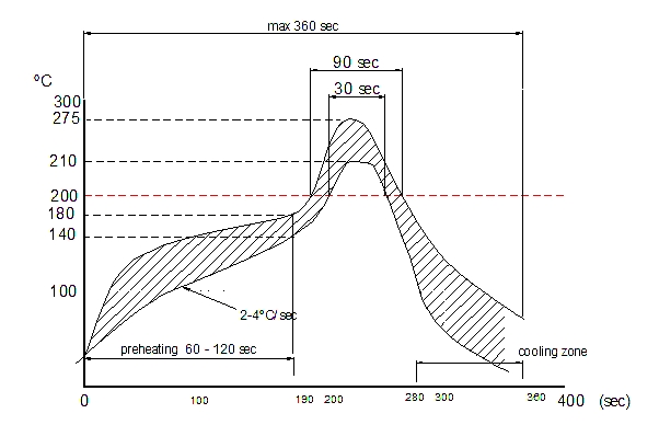
The reflow condition recommended is according to the machine used by our company. Big differences will arise as a result of the type of machine, reflow conditions, method, etc used.