TR1102 - X/Y axis SMD Ferrite RFID Transponder Inductor 125kHz / 2.38-9mH / 11x2.6x2.2mm
- picture_as_pdfDownload Data Sheet
- Characteristics
- Dimensions
- Packaging
- Cad Models
- Soldering
- Measurement Conditions


| Freq. (kHz) | L (mH) | Q Min | Sensitivity (mVpp/App/m) Min | Height (mm) | Length (mm) | Width (mm) | SRF (kHz) Min | Tolerance | Cres (pF) | DCR (Ω) Max |
|---|---|---|---|---|---|---|---|---|---|---|
| 125 | 9.00 | 24.3 | 75 | 2.2 | 11.0 | 2.6 | 280 | ±5% | 180 | 108 |
| 125 | 7.20 | 27 | 70 | 2.2 | 11.0 | 2.6 | 350 | ±5% | 220 | 90.2 |
| 125 | 4.91 | 30 | 50 | 2.2 | 11.0 | 2.6 | 420 | ±5% | 330 | 49 |
| 125 | 2.38 | 25 | 35 | 2.2 | 11.0 | 2.6 | 500 | ±5% | 680 | 40.7 |
| 125 | 1,08 | 31.5 | 25 | 2.2 | 11.0 | 2.6 | 900 | ± 5% | 1500 | 15.95 |
X/Y axis SMD Ferrite RFID Transponder Inductor
The TR1102 series of surface mountable ferrite wound inductor is the very first SMD coil designed for transponder use. Its length and cross sectional area are optimized to achieve the maximum sensibility in the coil axis. Its size is excellent for plastic moulded inmobilizer transponders.
The TR1102 is the best solution when both cost and high-speed assembly of the circuit components are sought.
|
The specification chart is a reference guide for the most common required values at working frequencies of 125 kHz. Any other inductance value at LF or tighter tolerances can be provided. Please contact our sales deparment for any inquiry.
This product has a datasheet available upon request.
| L (mH) | Tolerance | Q Min | Frequency (kHz) | Cres (pF) | SRF (kHz) Min | DCR (Ω) Max | Sensitivity (mVpp/App/m) Min | Length (mm) | Width (mm) | Height (mm) | |
|---|---|---|---|---|---|---|---|---|---|---|---|
| TR1102-0238J | 2.38 | ±5% | 25 | 125 | 680 | 500 | 40.7 | 35 | 11.0 | 2.6 | 2.2 |
| TR1102-0491J | 4.91 | ±5% | 30 | 125 | 330 | 420 | 49 | 50 | 11.0 | 2.6 | 2.2 |
| TR1102-0720J | 7.20 | ±5% | 27 | 125 | 220 | 350 | 90.2 | 70 | 11.0 | 2.6 | 2.2 |
| TR1102-0900J | 9.00 | ±5% | 24.3 | 125 | 180 | 280 | 152 | 75 | 11.0 | 2.6 | 2.2 |
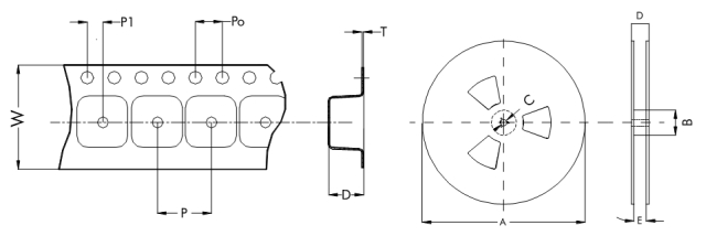
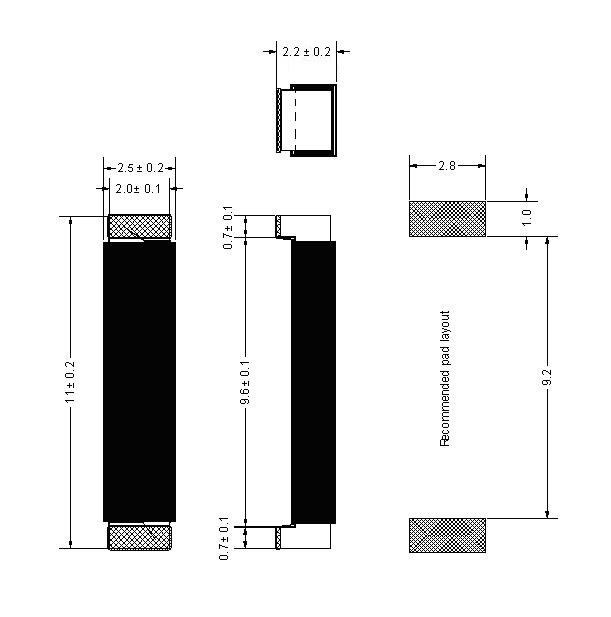
All dimensions in mm.


| Reel dimensions | Tape dimensions | PARTS/REEL | |||||||||
| A | B | C | D | E | W | P | P0 | P1 | D | T | |
| 330 | 50 | 13 | 30.4 | 24.4 | 24 | 4 | 4 | 2 | 2.5 | 0.3 | 5000 |
All dimensions in mm.
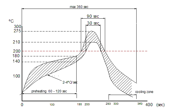
Recommended reflow profile.
Reflow soldering, vapour-phase soldering. A maximum soldering temperature of 260ºC during 10 s should not be exceed for (see recommended soldering profile with maximum and minimum temperature-time).

The reflow condition recommended is according to the machine used by our company. Big differences will arise as a result of the type of machine, reflow conditions, method, etc used.
- Rated Inductance LR: Measured at frequency fL, with impedance analyser WK3260 with 3MHz installed.
- Q Factor Qmin: Measured at frequency fL, with impedance analyser WK3260 with 3MHz installed.
- Self-resonance frequency fmin: Measured at frequency fL, with impedance analyser WK3260 with 3MHz installed.
- DC resistance Rmax: Measured at 20ºC ambient temperature, measuring current <IR.
- Sensitivity: Measured with Helmholtz coils 5 turns, 160mm ∅, + waveform generator Agilent 33120A + oscilloscope Agilent 54622A. Contact PREMO RFID for complete measurement specification.


