3DC15 3DCoil SMD 17.5x16x4 mm (2.47mH - 10mH)
- picture_as_pdfDownload Data Sheet
- Characteristics
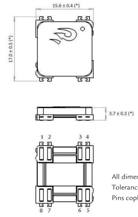
- Dimensions
- Packaging
- Cad Models
- Pad Layout
- Electrical Diagram
- Soldering
- Measurement Conditions
- Graphs
- Custom Product
- Others


| Freq. (kHz) | Lx (mH) | Ly (mH) | Lz (mH) | Qx Min | Qy Min | Qz Min | Height (mm) | Length (mm) | Width (mm) |
|---|---|---|---|---|---|---|---|---|---|
| 125 | 2.47 | 2.47 | 2.47 | 25 | 25 | 25 | 3.8 | 15.5 | 17.5 |
| 125 | 4.91 | 4.91 | 4.91 | 25 | 25 | 25 | 3.8 | 15.5 | 17.5 |
| 125 | 7.2 | 7.2 | 7.2 | 25 | 25 | 25 | 3.8 | 15.5 | 17.5 |
| 125 | 10 | 10 | 10 | 25 | 25 | 25 | 3.8 | 15.5 | 17.5 |
| 125 | 3.45 | 3.45 | 3.45 | 25 | 25 | 25 | 3.8 | 15.5 | 17.5 |
| 125 | 4.05 | 4.05 | 4.05 | 27 | 27 | 27 | 3.8 | 15.5 | 17.5 |
| 125 | 4.77 | 4.77 | 4.77 | 28 | 28 | 28 | 3.8 | 15.5 | 17.5 |
| 125 | 2.47 | 2.47 | 3.3 | 25 | 25 | 25 | 3.8 | 15.5 | 17.5 |
Keyless entry systems are a typical application for this coil, the Isotropy is often sought in RF antenna. In transponder applications, this feature has been achieved by the combination of 3 single coils oriented in the 3 space axis. The new 3D coil from PREMO RFID offers the possibility of mounting a single component instead of three, thus reducing cost, saving PCB space and increasing the circuit reliability. Sensitivity, low profile and small size are the key of this RFID innovative component. Best choice for keyless entry systems the three tri-rectangular windings ensure optimum field sensing regardless position.
- Size: 17.5 x 16 x 4mm
- High drop test resistance (up to 500 times 1 m) due to a maximized pin area.
- High stability in temperature (-40ºC to +125ºC).
- Isotropic version available.
- With cover cap or labelled.
- Taped & Reeled.
- Designed for 125KHz and 134KHz.
Applications:
- Automotive passive keyless entry systems.
- Automotive TPMS with wake up functions.
- Access control.
- Tracking devices.
The specification chart is a reference guide for the most common required values at working frequencies of 125 kHz. Any other inductance value at LF or tighter tolerances can be provided. Please contact our sales deparment for any inquiry.
This product has a datasheet available upon request.
| L x,y,z (mH) | Q x,y Min | Frequency (kHz) | Cres (pF) | SRF x,y (kHz) Min | SRF z (kHz) Min | DCR x,y (Ω) Max | DCR z (Ω) Max | Sensitivity x,y,z (mVpp/App/m) Min | Length (mm) | Width (mm) | Height (mm) | |
|---|---|---|---|---|---|---|---|---|---|---|---|---|
| 3DC15-0247J | 2.47 | >25 | 125 | 656 | 400 | 900 | 75 | 75 | 65 | 15.5 | 17.5 | 3.8 |
| 3DC15-0345J | 3.45 | >25 | 125 | 470 | 300 | 700 | 77 | 116 | 67 | 15.5 | 17.5 | 3.8 |
| 3DC15-0405J | 4.05 | >25 | 125 | 400 | 400 | 800 | 98 | 98 | 72 | 15.5 | 17.5 | 3.8 |
| 3DC15-0477J | 4.77 | >25 | 125 | 340 | 300 | 600 | 100 | 136 | 80 | 15.5 | 17.5 | 3.8 |
| 3DC15-0491J | 4.91 | >25 | 125 | 330 | 300 | 700 | 100 | 140 | 85 | 15.5 | 17.5 | 3.8 |
| 3DC15-0720J | 7.20 | >25 | 125 | 225 | 250 | 600 | 120 | 170 | 95 | 15.5 | 17.5 | 3.8 |
| 3DC15-1000J | 10 | >25 | 125 | 162 | 220 | 500 | 160 | 275 | 140 | 15.5 | 17.5 | 3.8 |
| 3DC15-S-0247J | 2.47 xy / 3.3 z | 25 | 125 | 6.56 | 400 | 900 | 50 | 90 | 65 | 15.5 | 17.5 | 3.8 |

.jpg)

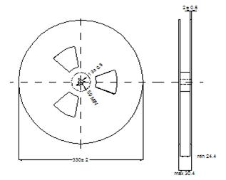
| Reel dimensions | Tape dimensions | PARTS/REEL | |||||||||
| A | B | C | D | E | W | P | P0 | P1 | D | T | |
| 330 | 50 | 13 | 30.4 | 24.4 | 24 | 20 | 4 | 2 | 4.2 | 0.3 | 600 |
All dimensions in mm.
Steps to download CAD Model:
1. Click on right button on "DOWNLOAD CAD MODEL"
2. Select "save link as"
3. Save the document on your computer.
.jpg)

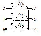
If the three coils from this component are going to be connected to a common GND; pins 1, 7 and 8 should be the chosen ones as common connection in order to keep the electromagnetic characteristics of the part.
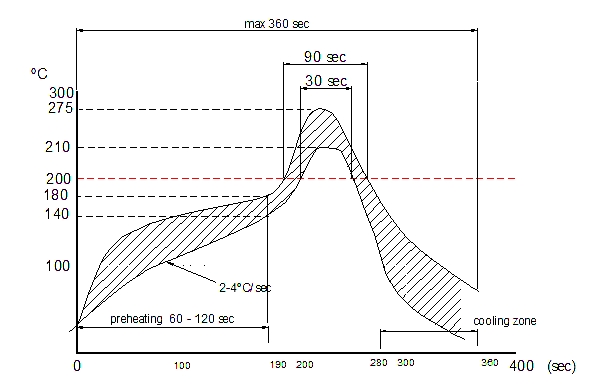
Recommended reflow profile.
Reflow soldering, vapour-phase soldering. A maximum soldering temperature of 260ºC during 10 s should not be exceed for (see recommended soldering profile with maximum and minimum temperature-time).

The reflow condition recommended is according to the machine used by our company. Big differences will arise as a result of the type of machine, reflow conditions, method, etc used.
- Rated Inductance LR: Measured at frequency fL, with impedance analyser WK3260 with 3MHz installed.
- Q Factor Qmin: Measured at frequency fL, with impedance analyser WK3260 with 3MHz installed.
- Self-resonance frequency fmin: Measured at frequency fL, with impedance analyser WK3260 with 3MHz installed.
- DC resistance Rmax: Measured at 20ºC ambient temperature, measuring current <IR.
- Sensitivity: Measured with Helmholtz coils 5 turns, 160mm ∅, + waveform generator Agilent 33120A + oscilloscope Agilent 54622A. Contact PREMO RFID for complete measurement specification.


