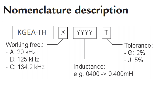
KGEA-TH-B-0345J
Keyless go emitter antenna winding heat...
5,00 €
61 In Stock
Menus


| Freq. (kHz) | L (µH) | Length (mm) | Width (mm) | Height (mm) | SRF (MHz) Min | Q Min | Cres (nF) |
|---|---|---|---|---|---|---|---|
| 125 | 345 | 75 | 15 | 6.3 | 1.5 | 125 | 4.7 |
| 125 | 500 | 75 | 15 | 6.3 | 1.5 | 125 | 3.3 |
This emitter antenna is specifi cally designed for applications in which it is necessary to get a big read range with a minimum size on PCB in low frequency base stations (125 and 134.2 KHz).
It is a perfect solution to be used in vehicles passive entry applications (PE, passive entry) or TPMS (Tyre Pressure Monitoring system), especially when high mechanical stress is involved.
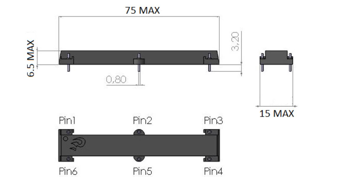
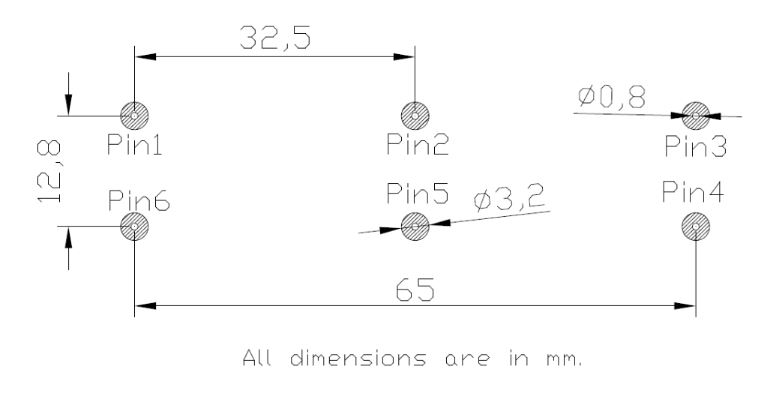
It has 75mm x 15mm x 6.3mm for conventional through-hole assembly. The module
antenna is formed only by ferrite core wound inside of a plastic housing and it fi lled with resin of polyurethane.
The specification chart is a reference guide for the most common required values at working frequencies of 125 kHz, 20 kHz and 134.2 kHz. Any other inductance value
at LF or tighter tolerances can be provided. Please contact our sales department for any inquiry.
| L (mH) | Q Min | Frequency (kHz) | SRF (MHz) Min | Length (mm) | Width (mm) | Height (mm) | |
|---|---|---|---|---|---|---|---|
| KGEA-TH-B-0345J | 0.345 | 125 | 125 | 1.5 | 75 | 15 | 6.3 |
| KGEA-TH-B-0500J | 0.500 | 125 | 125 | 1.5 | 75 | 15 | 6.3 |
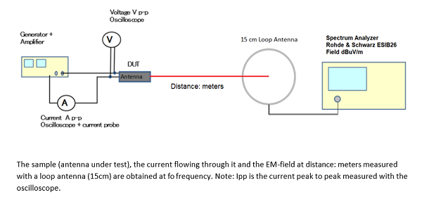
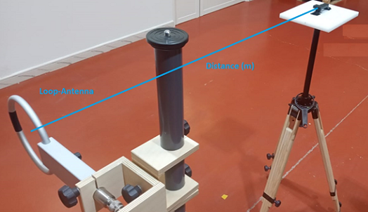
| H‐Field (1m) @ 125KHz (dBuV/m) | H‐Field (2m) @ 125KHz (dBuV/m) | H‐Field (3m) @ 125KHz (dBuV/m) |
|---|---|---|
| Ipp=2App | Ipp=2App | Ipp=2App |
| 136.2 | 119.75 | 109.7 |