TP0702CAP-0238J
X/Y axis SMD Hard Ferrite Transponder Coil...
5,00 €
150 In Stock
Menus


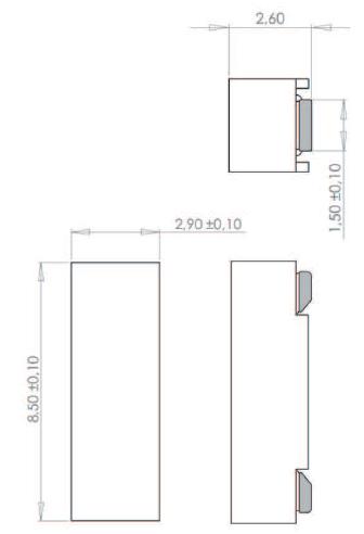
| Freq. (kHz) | L (mH) | Q Min | Sensitivity (mVpp/App/m) Min | Height (mm) | Length (mm) | Width (mm) | SRF (kHz) Min | Tolerance | Cres (pF) | DCR (Ω) Max |
|---|---|---|---|---|---|---|---|---|---|---|
| 125 | 2.38 | 20 | 25 | 2.7 | 8.6 | 3 | 750 | ±5% | 680 | 51 |
| 125 | 4.91 | 22 | 50 | 2.7 | 8.6 | 3 | 500 | ±5% | 330 | 71 |
| 125 | 7.20 | 18 | 47 | 2.7 | 8.6 | 3 | 450 | ±5% | 220 | 147 |
| 125 | 9.00 | 18 | 47 | 2.7 | 8.6 | 3 | 400 | ±5% | 180 | 165 |
This TP0702 with CAP is a very strong solution in very small dimensions. The
component has very good electrical properties and it is a very good solution for RTPMS,
Keyless Go and Keyless Entry Systems. On the other hand, the plastic box, where it is
inserted the piece, offers a special protection to the wound and facilitates the pick and
place
|
Due to its small dimensions, it’s a suitable design for other applications working at lower frequencies.
The specification chart is a reference guide for the most common required values at working frequencies of 125 kHz. Any other inductance value at LF or tighter tolerances can be provided. Please contact our sales deparment for any inquiry.
This product has a datasheet available upon request.
| L (mH) | Tolerance | Q Min | Frequency (kHz) | Cres (pF) | SRF (kHz) Min | DCR (Ω) Max | Sensitivity (mVpp/App/m) Min | Length (mm) | Width (mm) | Height (mm) | |
|---|---|---|---|---|---|---|---|---|---|---|---|
| TP0702CAP-0238J | 2.38 | ±5% | 20 | 125 | 680 | 750 | 51 | 25 | 8.6 | 3 | 2.7 |
| TP0702CAP-0491J | 4.91 | ±5% | 22 | 125 | 330 | 500 | 71 | 50 | 8.6 | 3 | 2.7 |
| TP0702CAP-0720J | 7.20 | ±5% | 18 | 125 | 220 | 450 | 147 | 47 | 8.6 | 3 | 2.7 |
| TP0702CAP-0900J | 9.00 | ±5% | 18 | 125 | 180 | 400 | 165 | 47 | 8.6 | 3 | 2.7 |
.jpg)
.jpg)
![]()
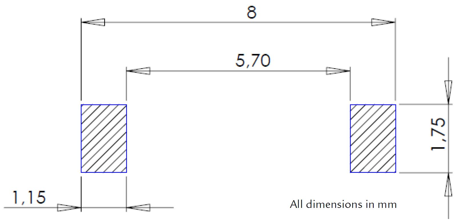
| Reel dimensions | Tape dimensions | PARTS/REEL | |||||||||
| A | B | C | D | E | W | P | P0 | P1 | D | T | |
| 330 | 50 | 13 | 30.4 | 24.4 | 16 | 8 | 4 | 2 | 2.9 | 0.3 | 2500 |
All dimensions in mm.
Reflow soldering, vapour-phase soldering. A maximum soldering temperature of 260ºC during 10 s should not be exceed for (see recommended soldering profile with maximum and minimum temperature-time).
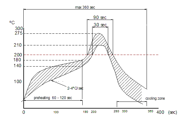
The reflow condition recommended is according to the machine used by our company. Big differences will arise as a result of the type of machine, reflow conditions, method, etc used.